Creating a RAID Array: Building a PC and Hardware Selection Guide
Interested in building a PC with a RAID array but not sure where to start? You’re in the right place! In this article, we’ll provide you with an essential guide to creating a RAID array, building a PC, and selecting hardware for RAID. From understanding RAID levels to choosing the right components for your build, we’ll walk you through the process step by step. Whether you’re looking to enhance data redundancy or improve disk performance, building a PC with a RAID array can help you achieve your storage goals.
- PC parts
- Assembling a PC
- Step 1. Central processor
- Step 2. Installing the CPU cooler
- Step 3. Installing system memory
- Step 4. The case and power supply unit
- Step 5. Installing the motherboard into the case
- Step 6. Connecting the PSU to the motherboard
- Step 7. Connecting the motherboard to the case
- Step 8. Installing and connecting hard disks
- Step 9. Installing the graphics card
- Installing the operating system
- Questions and answers
- Comments
All modern motherboards come equipped with an integrated RAID controller, and top models may have several such controllers on board. That’s a different question, though, if such integrated controllers in consumer-class motherboards are ever used by an average user. Anyway, some motherboards do give a chance to setup a RAID array right inside your home PC.
Below are brief recommendations on building a RAID array on a home computer and a practical tutorial on assembling a PC for RAID.

💿 Data Recovery Tool for Damaged RAID Arrays 💿
PC parts
First of all, you need to decide on the purposes for which you want to build a RAID system on your computer, and the RAD type you are going to use.
Check our dedicated article on RAID types, their architecture and how they work.
When you decide on the RAID type, choose a motherboard supporting such arrays and having a sufficient number of SATA ports to work with the required number of disks.
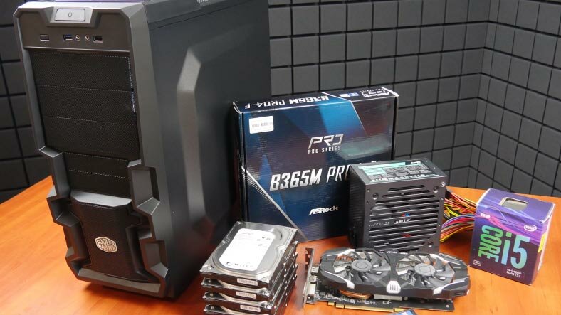
For our needs, we decided to build a configuration for RAID 5. Here is the list of hardware we selected for this purpose:
- ASRock B365M Pro4-F motherboard with RAID 0, 1, 5, 10 support and six SATA ports for hard disks;
- A spacious Cooler Master K380 case with several slots for HDDs;
- i5-9400F, a 9th generation Intel processor;
- One 16 GB (2400 MHz) system memory module by Kingston;
- nVIDIA GeForce GTX 1060 graphics card.
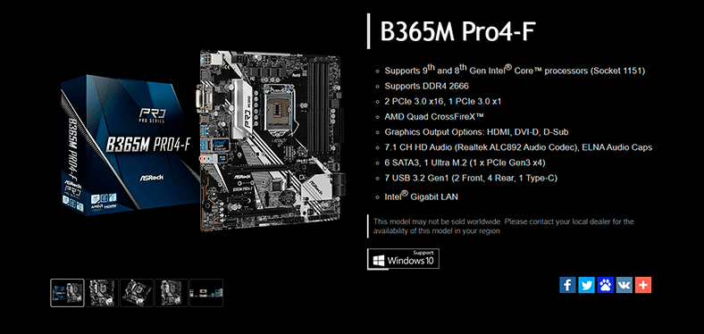

| Specification | Description |
|---|---|
| Form Factor | Micro ATX |
| Chipset | Intel B365 |
| Processor Support | Intel Core 8th and 9th Generation (Socket 1151) |
| Memory Slots | 4 x DDR4 DIMM, up to 64 GB, frequency up to 2666 MHz |
| Memory Support | Dual-channel, support for ECC and non-ECC memory |
| Expansion Slots | 1 x PCIe 3.0 x16, 2 x PCIe 3.0 x1 |
| Storage Ports | 6 x SATA 6 Gbps, 2 x M.2 (one supports PCIe Gen3 x4 & SATA) |
| RAID Support | RAID 0, RAID 1, RAID 5, RAID 10 (for SATA devices) |
| Integrated Graphics | Supports Intel UHD Graphics with HDMI, DVI-D, D-Sub outputs |
| USB Ports | 6 x USB 3.1 Gen1 (4 on the rear panel, 2 via internal connectors), 6 x USB 2.0 |
| Audio | 7.1-channel Realtek ALC887 audio |
| Network Card | Realtek RTL8111H, 1 Gbps Ethernet |
| BIOS | UEFI AMI |
| Fan Connectors | 2 x CPU Fan, 2 x chassis fan |
| Dimensions | 244 mm x 244 mm |
Assembling a PC
Now that we have got all the parts, let’s start building the computer.
Step 1. Central processor
The first step is to install the processor and the system memory onto the motherboard.
It’s not that difficult at all – just find out how to place the CPU into the socket. If you are building a computer for the first time, never try to push or force the processor into the socket if it doesn’t fit – it never helps, but you can bend the pins or end up with a damaged processor. If you position the processor into the socket properly, it will fit into its place easily.
On the processor, there is a triangular mark in the corner, and a similar mark on the socket of your motherboard. Position the processor in such a way that the marks coincide.
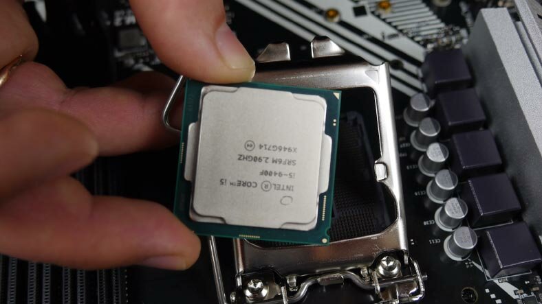
Also, on the edges of the processor there are small notches that are meant to fit into the corresponding elements on the socket.
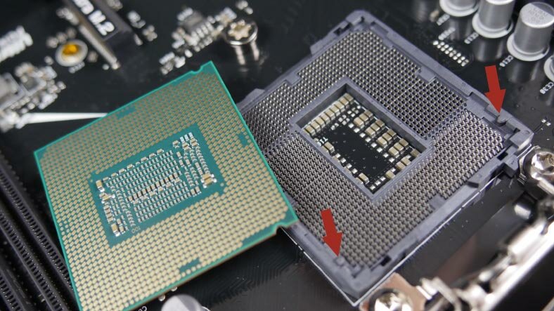
Install the processor and fix it with the latch.
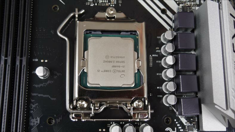
All right, the CPU is now in its proper place.
Step 2. Installing the CPU cooler
The next step is applying the thermal paste and installing the processor’s cooler. In my case, the stock cooler comes with the thermal paste on it, so I skip the paste part and just install the cooler.
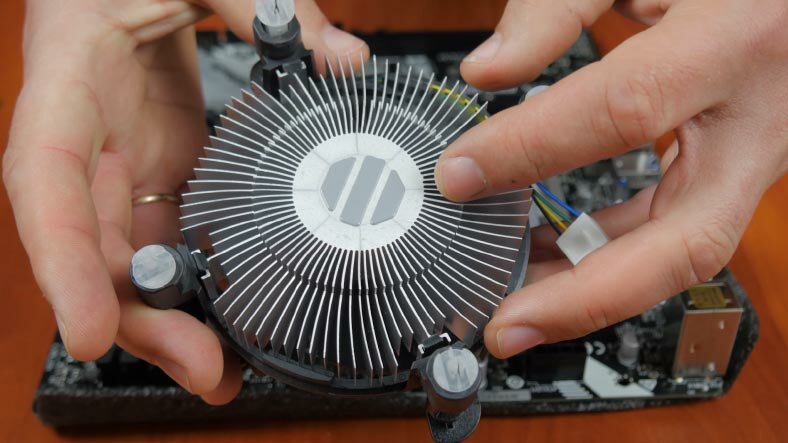
Push the locking pins through the holes in the motherboard and secure them by turning.
All coolers always come with an installation manual, so read it carefully before you start, and there won’t be any problems with installing the cooler.
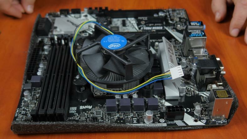
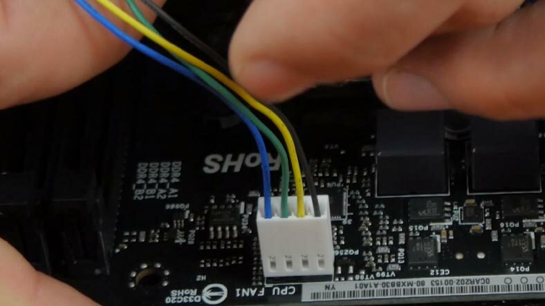
The final step is to connect the cooler to the motherboard. The plug at the end of the cable coming from the fan should be inserted into the connector marked as CPU_FAN. The actual location of the connector depends on the particular motherboard model, but the marking is always the same.
Step 3. Installing system memory
Now insert the system memory into the memory slot and put the motherboard aside.
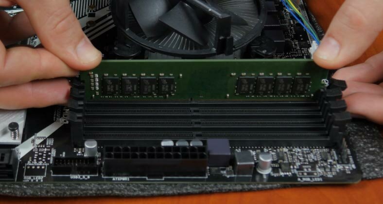
To install the RAM modules, open the retention clips and put the module into the slot.
Bear in mind, that system memory modules should be inserted only in a certain position. If the module won’t fit into the slot, just try turning the module the other side. Inserting the modules doesn’t need much physical pressure so don’t force the module if it won’t fit.
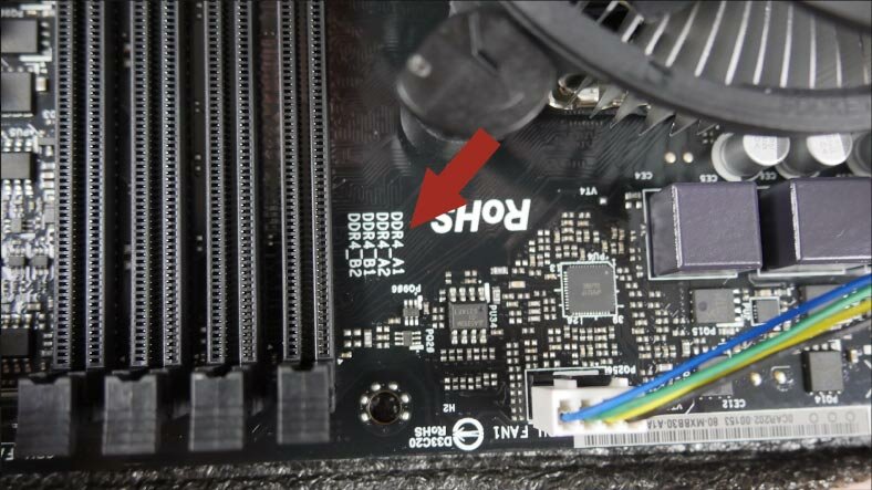
The motherboard may also have special marking and numbers for slots. If you have two RAM modules, place them into slots 1 and 2. If you have a single module, put it into slot 1.
Put the motherboard aside and grab the case. Now we are going to install the power supply unit and do a bit of cable management.
Step 4. The case and power supply unit
Install the PSU into the designated place inside the case and secure it with the fastening screws which come supplied with the unit.
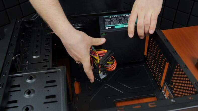
Lay the cables behind the side panel on which the motherboard will be mounted. Push the cables through the openings: motherboard power – into the upper hole, and the rest of the cables – into the lower hole.
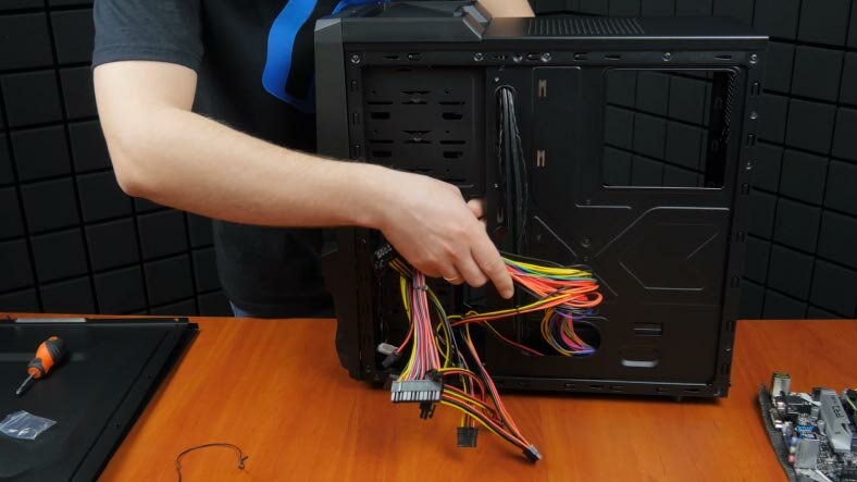
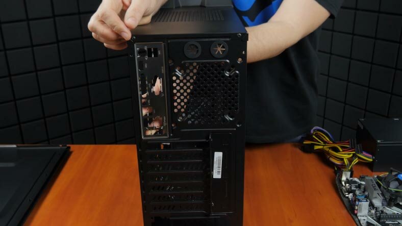
Check the motherboard packaging box for a metal backplate, also known as IO shield. Insert it in the rear of your case according to the position of the motherboard. Do it from the inside of the case and push slightly until it clicks into place.
Step 5. Installing the motherboard into the case
Then have a look at how your motherboard fits into the case to find out where you should prepare additional mounting points. Usually these elements (also called standoff screws) come with the computer case.
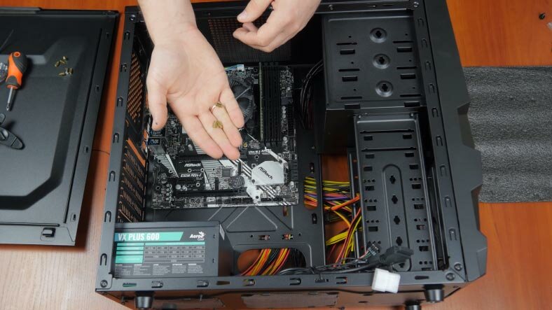
Screw them into the back panel according to how mounting holes are positioned on the motherboard. Now check the motherboard again to make sure the holes coincide with the standoff screws. Now fix it to the case with the screws that come supplied with the case.
Step 6. Connecting the PSU to the motherboard
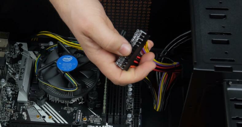
At this stage, it’s time to connect the motherboard to the power supply unit.
Connect the CPU power cable – it’s got an eight-pin connector,
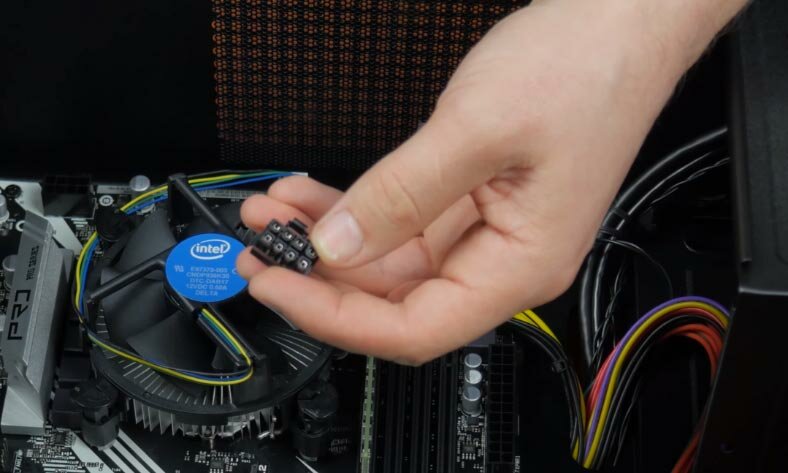
And this thick cable which delivers power to the motherboard.
Step 7. Connecting the motherboard to the case
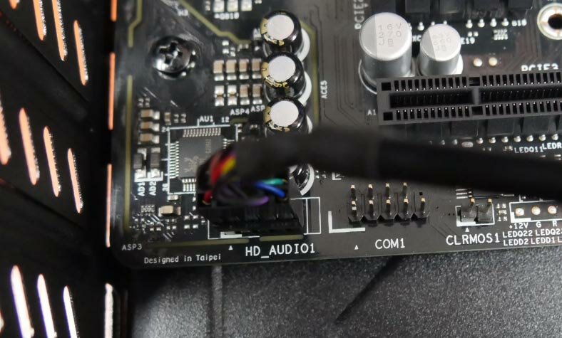
Now we are ready to connect the motherboard and the case front panel. At this stage you may have some difficulties if you’re building a computer for the first time, especially when you need to connect the front panel indicators / lights. Don’t worry – all plugs and all motherboard connectors come with the corresponding markings.
It’s very easy – put the AUDIO plug into the AUDIO connector – just pay attention to the location of the connectors and remember that if you are trying to put something in the wrong place, it won’t fit in.
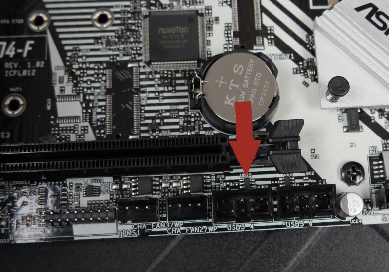
After that, insert the USB plug into USB1 or USB2 connector, and it doesn’t matter which one you choose.
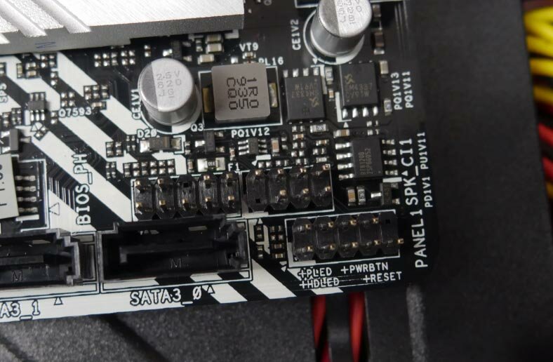
Now it’s time to connect the Power and Reset buttons, as well as LED indicators. Read the motherboard manual to find their exact location. Electric polarity is usually marked on the motherboard and the plugs.
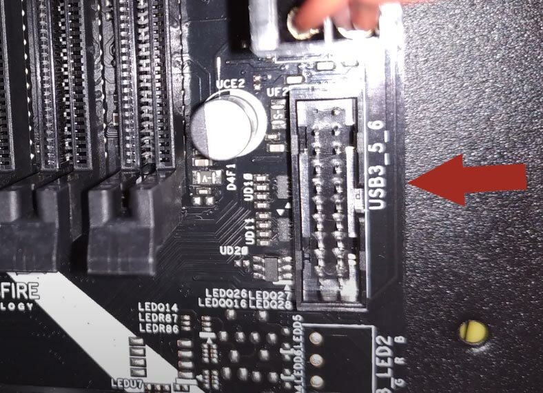
Also, don’t forget to connect the USB 3.0 cable – everything is marked accordingly, too.
Step 8. Installing and connecting hard disks
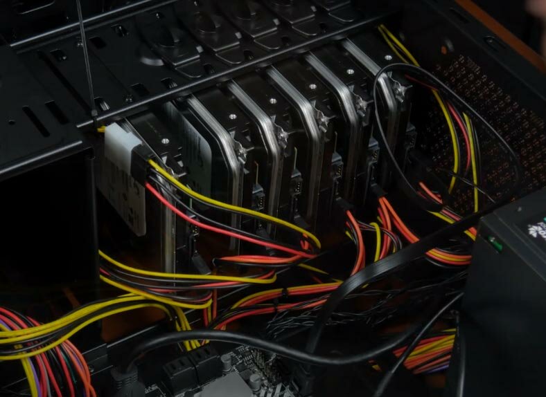
Let’s move on to adding hard disks. For our RAID system, we are going to use 6 Western Digital drives, 320 GB each. Install them, fix them with special screws, plug power cables into corresponding connectors and use SATA cables to link the disks with the motherboard. As there are less power cables for all disks than we need, suitable power adapters are required.
Step 9. Installing the graphics card
Finally, add the graphics card.
Take the card and try positioning it inside the case, to see which part of the metal backplate / IO shield should be removed. Then just insert the card into the PCI Express slot and use a screw or two to secure the graphic card’s metal retention bracket to the case so that is fixed into place firmly. As the final step, plug the additional power cable into the corresponding connector on the graphics card.
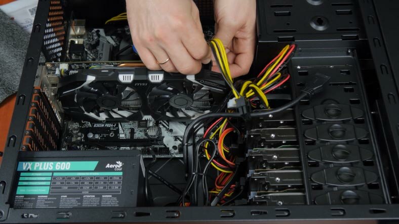
Congratulations: the computer is now assembled.
Installing the operating system
Now that the computer is in one piece, you need to configure RAID in BIOS and install an operating system.
Open BIOS, jump to Advanced mode – Storage Configuration – Intel Rapid Storage Technology.
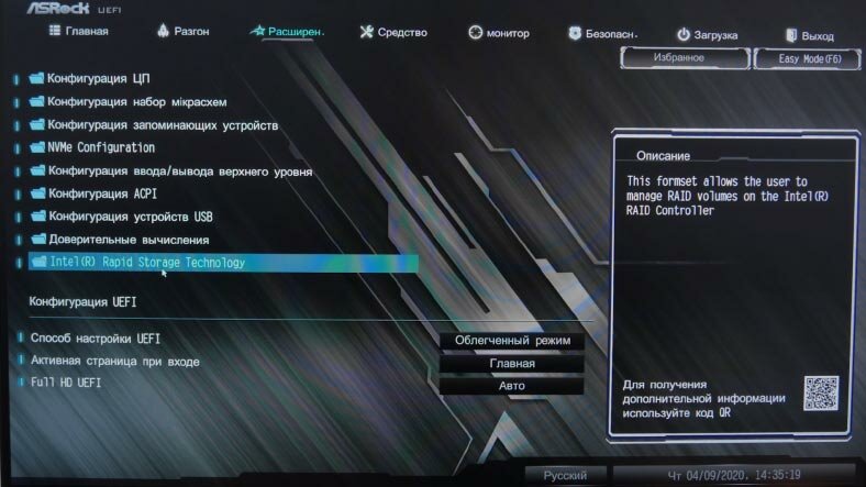
Select Create RAID volume. Specify the name, choose RAID type and select the disks you are going to use with it. Click Create Volume below – Save changes and exit.
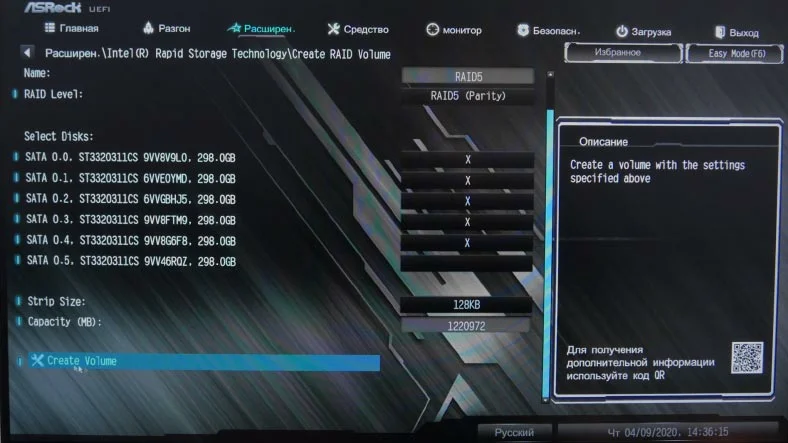
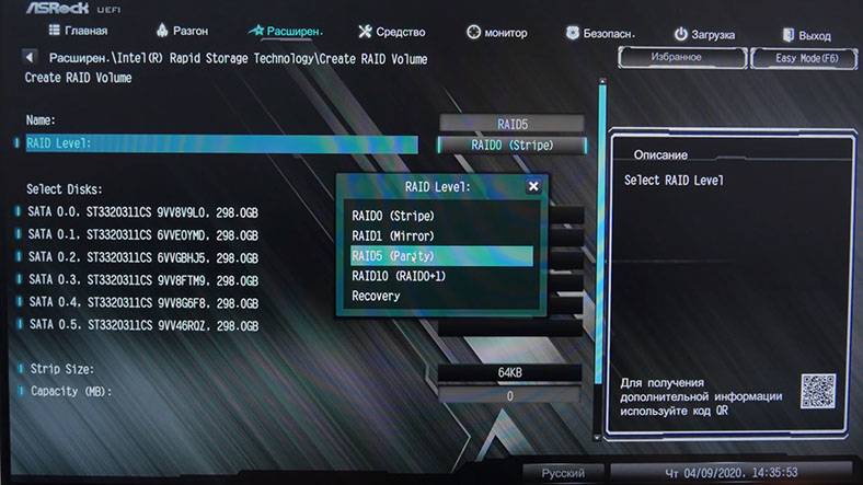
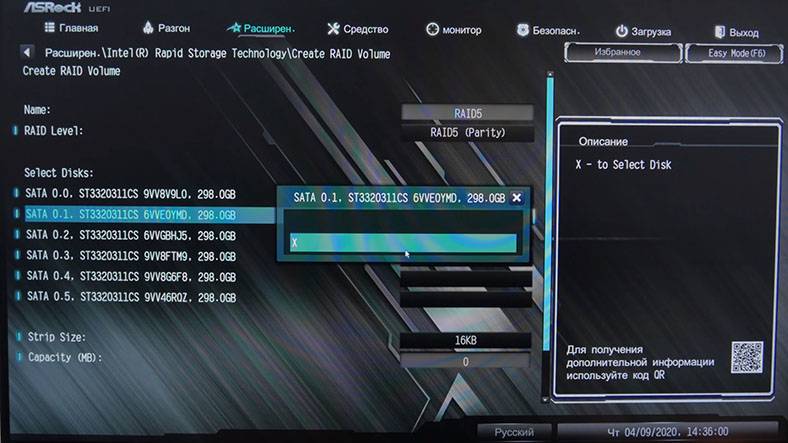
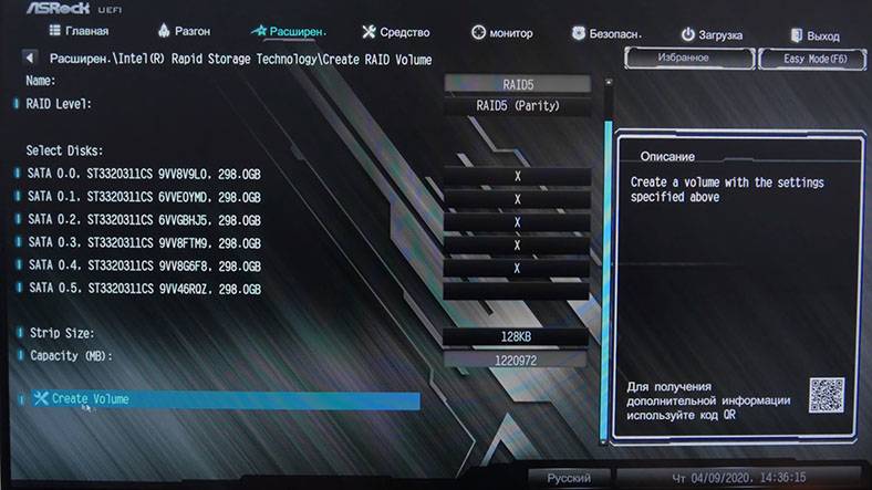
The last step is to install an operating system. This task requires a bootable USB drive or disk.
You can visit either our blog or YouTube channel for a detailed article or video on creating such a drive and installing an operating system.
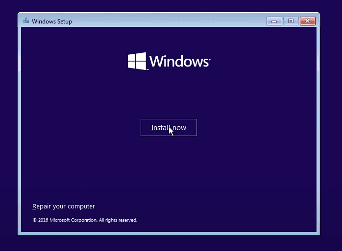
Nothing special here: boot from the USB drive, select your language, enter the license key, choose version of the operating system, accept the agreement and so on – the same steps we all have to follow when installing Windows.
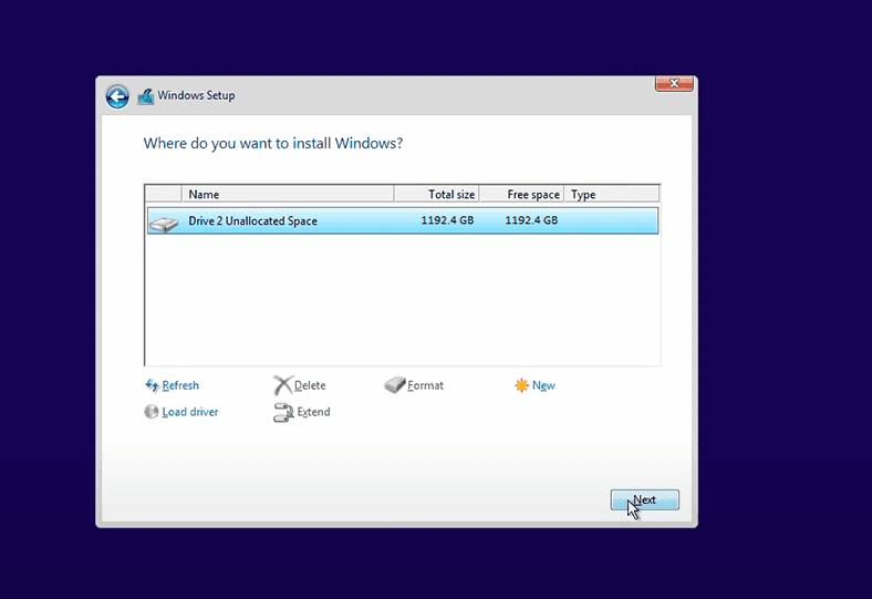
At the next stage, select the disk for installation. You can see that the computer detects one disk with the capacity of 1192.4 GB. This is our RAID system. Select it and click Next.
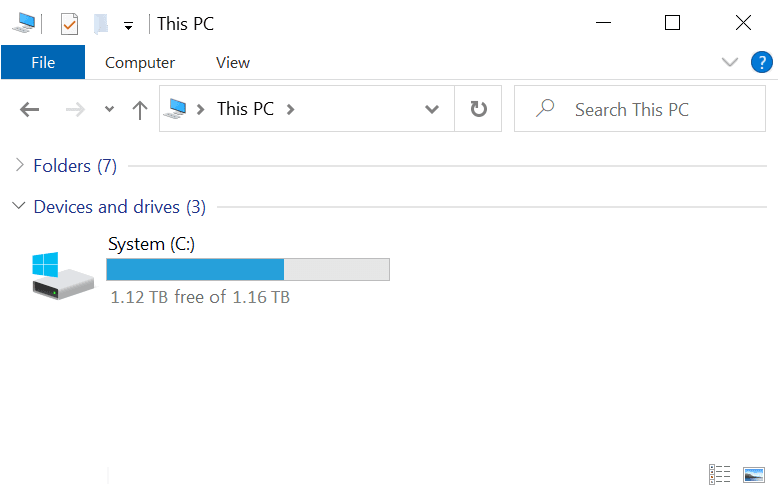
The operating system is installed. When you open This PC, you will see the disk of 1.16 TB.
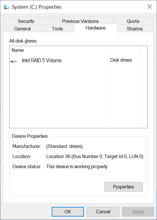
Open its properties to find out that this is the RAID 5 array we have just created.
That is all. Hopefully, this article helped you to understand how to set up a RAD system on a home computer.
Check one of the previous articles in our blog on various types of RAID systems.

🏆 How to Recover a Crashed RAID 5EE After Controller Failure or Multiple Disk Failure 🏆


